
- This topic has 30 replies, 3 voices, and was last updated 7 years, 4 months ago by
Klaatu.
-
AuthorPosts
-
-
27 December 2018 at 18 h 41 min #43896
Scudie
ParticipantHave built a Seeburg Sc1 with all the workings transformer etc including the wb2mp3 board inside it.
The wallbox that I bought was missing its credit unit so I had to figure a way of putting it in free play with out the credit unit.
I have also found a way of utilising the three volume control buttons on the front of the machine if any one is interested on doing this on there own Seeburg Sc1-4 I can help with a description / diagram of how these were done. -
4 January 2019 at 18 h 06 min #43910
Klaatu
KeymasterHello,
Let us know how you did it for the volume buttons.
I did it too but with a cdadapter, and though it was possible with the wallbox2mp3 because only one ground channel…
-
4 January 2019 at 21 h 33 min #43913Participant
Hello , Bonsoir
Yes you are correct the Seeburg consolettes use a common ground for both speakers, & this is not allowed with the wb2mp3 unit as the speaker grounds / negatives have to be kept separate.
I will post an explanation with photo’s during the weekend, my photos of this are on my phone which is not currently available.
Cheers Scudie
-
5 January 2019 at 16 h 29 min #43915Keymaster
Curious to see your solution. I have another Seeburg SC1 to convert.
-
6 January 2019 at 21 h 15 min #43918Participant
This is how I achieved working volume control buttons on a Seeburg SC 1-4 wallbox.
First of all this description is for models that have a speaker relay located behind the volume switches, the SCH models that take half dollar coins are slightly different and are not covered in this description. (They can be done)
First remove the screws that secure the switch unit and the single screw that secures the relay, the relay screw is accessed from the underside.
Then identify the two wires that Connect the switch unit to the relay these are normally green with a white trace and yellow with a white trace but can also be white with a green trace and white with a yellow trace.
For ease of access I un solder these two wires after noting their positions on the relay.
Take note of the speaker wire positions and disconnect the four speaker wires then loosen the screw on the large terminal block that is marked GRY there should be three wires, they are normally grey but could be white with a grey trace.
You should now have the volume switch completely free, on the underside of the volume switch you will see three pairs of resistors, The 2 ten ohm resistors (brown two black and grey/ silver stripe) are located at the low button end of the board these two resistors are connected to a common terminal which will also have a single grey or white and grey wire connected to it.
The 2 Ten ohm resistors have a brown two black and a silver stripe on them, if you hold the board lengthways with these two resistors closest to you there should be a yellow speaker wire on the left and the green speaker wire on the right.
You need to separate the 2 ten home resistors, I cut the left hand resistor as close to the soldered central connection as possible then solder a new length of wire to the free leg of the resistor, insulate it and then put a blob of glue (hot glue gun) to bridge the gap to the board to give it some stability.
Now remove the board from the mechanical section of the switch and clean all the terminals and there associated sliding contacts, these are on the opposite side of the board to the resistors.
Reassemble the cleaned and modified volume switch.
Now back to the three ground wires that were disconnected from the terminal block one will go to the right-hand speaker ground, one will be connected to the United modified ten ohm resistor, the third will go to the left-hand speaker ground.
The left-hand speaker ground wire needs to be separated from the other two and then paired with the new wire that was soldered to the left hand ten ohm resistor.
As there is insufficient space on the main terminal block for left hand speaker ground wire and its new 10 ohm resistor wire, I use the redundant coin switch terminal block this will have three wires which I remove and insulate, one red, one brown, one orange, that come from the coin switch, once removed the terminal block can be used for the left hand speaker ground.
Before re-fitting the components it’s worth taking the time to clean the contacts of the speaker relay, once cleaned I fit a small cable tie around the relay to hold the contracts permanently closed.
Once you have reassembled and reconnected the switch unit and the relay, including there associated wires the speaker wires from the wb2mp3 unit can be connected to their respective terminals on the two terminal blocks.Hope this helps Cheers Scudie.
-
6 January 2019 at 21 h 30 min #43919Participant
-
6 January 2019 at 21 h 32 min #43920Participant

-
6 January 2019 at 21 h 36 min #43921Participant
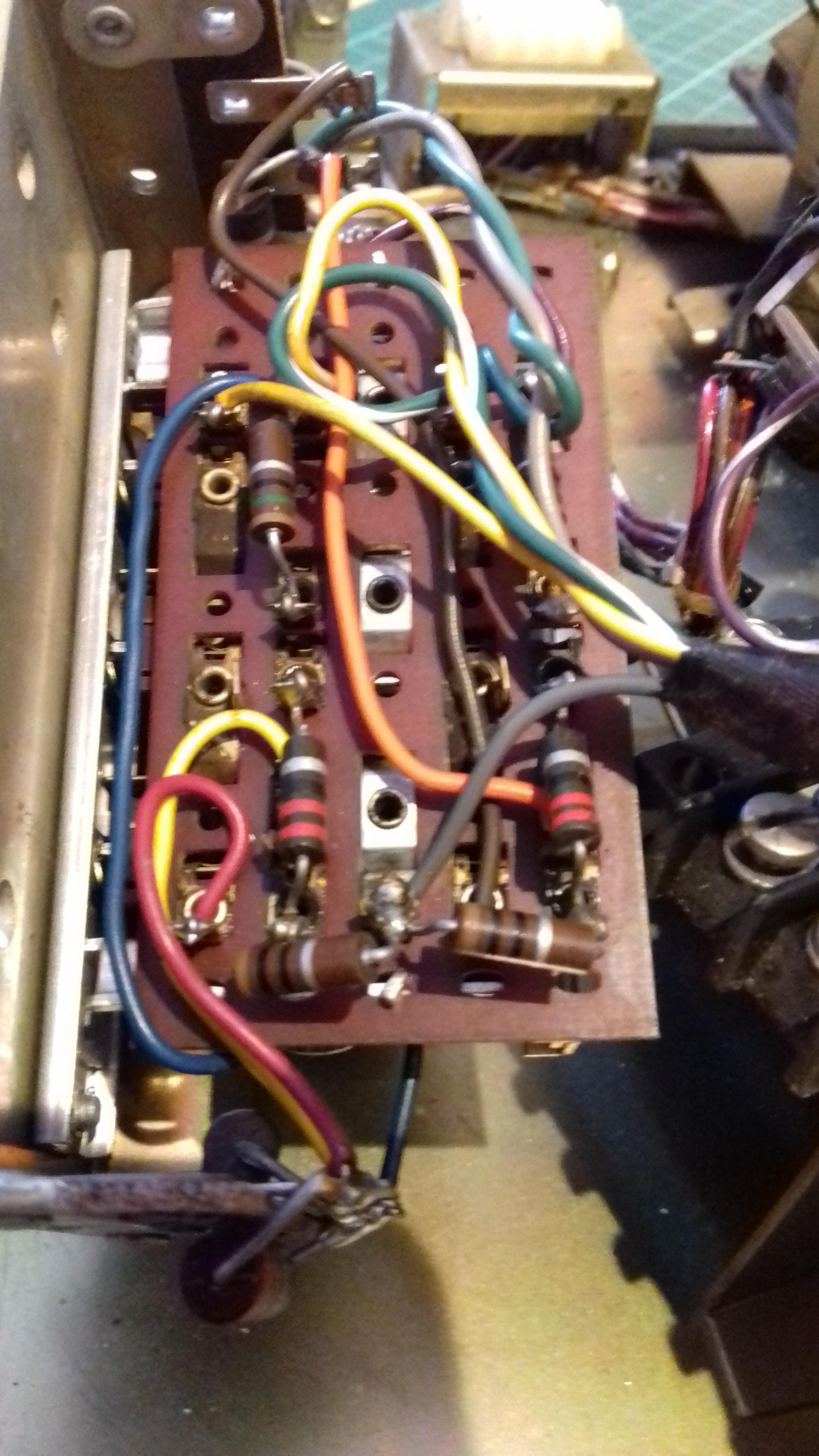
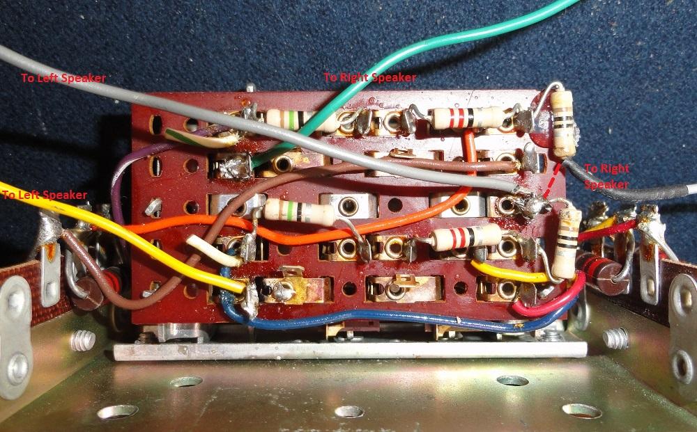
The first photo is of a un modified volume switch the second one shows the ten ohm resistors separated and with the new wire connected (brown)
Cheers Scudie
-
7 February 2019 at 4 h 08 min #44037Keymaster
Great more difficult to explain than to do it 😉
Will try some day, if I redo a Seeburg SC1.
-
7 February 2019 at 23 h 03 min #44038Participant
Yes you a right it is quicker to remove the switch unit, convert it & clean all the contacts than it is to type out a description of how to do it. Especially if you type like me rather steadily. I have also done one SCH machine these differ slightly because the speaker wires go through the credit unit & have no speaker relay. They have a 15 pin connector for the credit unit plug apposed to the normal 12. Again the credit unit had been removed to make space for an LED control unit and remote sensor. I think they routed the speaker wiring like this to stop people listening to selections made by other people. Will have to take the cover off of it and take a look how I wired it, the mod on the resistor board is the same.
Cheers Scudie
-
24 February 2019 at 18 h 12 min #45955
Sooner
ParticipantScudie – Thanks for posting this. I figured out what you’ve done and plan on using it when my emulator arrives. I’m curious how you wired the speakers from the wallbox2mp3 . Did they go through the relay or directly to the speakers/volume button mechanism.
-
24 February 2019 at 18 h 43 min #45956Participant
Hello Sooner
I guess you could bypass the volume control relay, I have normally cleaned the contacts of the relay then placed a small tie wrap around it so that the contacts are held in the closed position & disconnected the power to stop the relay energising so that it can’t overheat.
-
26 February 2019 at 2 h 07 min #45958Participant
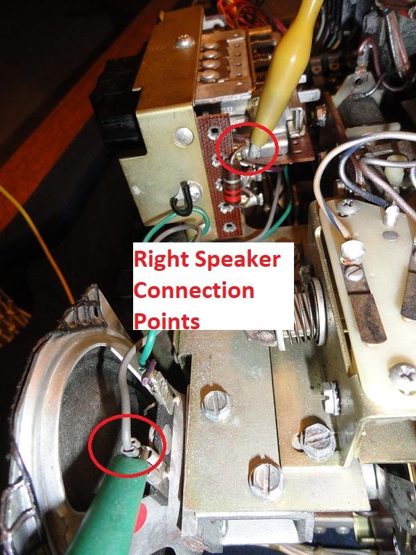
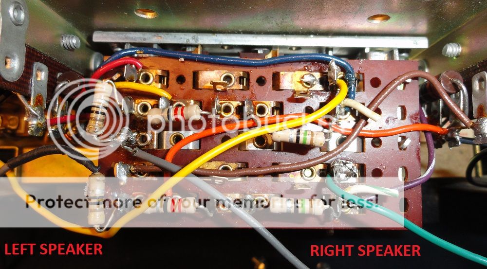
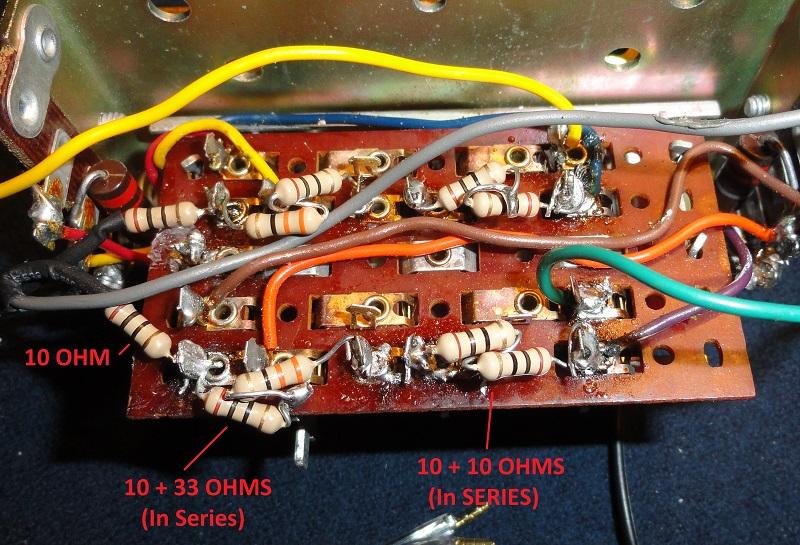
Here are a couple of photos of how I set mine up to bypass the relay and use the volume control buttons. The first photo shows I basically did the same thing as scudie. I separated the 10 ohm resistor and attached a wire to the end. Instead of taking the grey wires back to the terminal block I took them straight to the speakers. I don’t have my wallbaox2mp3 unit yet so I tested it with my iPod. The second photo shows the connections points coming from the iPod. The positive goes to the top terminal on the right hand side of the volume control unit and the negative goes to the speaker.
Thanks again scudie for the tip!
-
2 March 2019 at 0 h 42 min #45964Participant
Scudie – I received my emulator and tested it out today. First I should note that the photo above is incorrect. I had to reverse the grey wires to get it to work. The revised wiring is shown below. It works well using my iPod but with the emulator there is distortion on the Low and Medium settings. It’s particularly noticeable on the Low setting. Do you notice any distortion on yours with the Low setting? Also can you please explain how you have the positive side of the speakers are connected?
Thanks,
 Steve
Steve -
3 March 2019 at 15 h 46 min #45969Participant
Hello Steve
Yes the distortion that you mention is a known problem, there are several posts on the forum that talk of a humming / buzzing from the left speaker, some of the posts are in English and others if French.
I have been told that Fabien is currently looking into this issue with a view to eradicating it.
I am not 100% sure what you mean by How I have the speaker + connected, all I can tell you is that both audio output positives from the wb2mp3 board connect to the large terminal block using the connections marked YEL & GRN
Hope this helps Scudie
,
-
3 March 2019 at 18 h 55 min #45971Participant
Yes that helps. I didn’t see any directions in the manual for how to hook the speakers up. I actually have two noise issues. The low level buzzing occurs on both speakers but is only noticeable when the volume control on the Wallbox2mp3 unit is very low.
The other issue is distortion that occurs when I set the Seeburg volume to low using the push button mechanism. I think I have the modification to the mechanism done similar to what you did so I’m wondering if you notice distortion when you set your volume button on low.
I also notice when mine is set on low the sound becomes mono instead of stereo so I suspect there is still some connection between speaker grounds. The same thing happens on the medium volume setting but to a lesser degree.
-
3 March 2019 at 20 h 03 min #45973Participant
Hi again
I have not noticed any noticeable level of distortion of sound quality, in any of the volume switch position settings, with the three buttons level ie non pressed in, I get a very low volume level, with the low button depressed the volume rises ,with med button depressed a little louder, and the highest volume achieved with the high button pressed. The rise in volume for each stage is quite subtle.
I was wondering if you had cleaned the electrical contact surfaces of the volume switch components while you were modifying the resistor section? Or do you have a damaged speaker cone?
Cheers Scudie
-
3 March 2019 at 20 h 19 min #45974Participant
My speakers are good. There’s no distortion on the high setting and it’s not really noticeable on the medium setting. I didn’t clean the contact surface because they looked good. I can try that but don’t think it will help.
From your post I think I had mine set up like yours in the first photo I posted. I think I have mine reversed from what you did but not positive. I do get a modest volume change between the 3 buttons but the distortion is noticeable on the low setting. Also I tried it with a music file that only had music on ones speaker. It played fine on High but on medium and low settings there was sound coming from both speakers. I’m pretty sure there is still some connection between the two speaker grounds on the low and medium settings. I plan on trying to get a schematic for the volume control and see if I can figure out what’s going on. I tried to draw the schematic myself but can figure out exactly what the switches are doing without taking it completely apart. You might listen again closely and see if you get distortion on the low setting and see if it becomes mono instead of stereo.
I got your emails from wallbox2mp3.com. I can’t reply to them so I’m replying here. Didn’t realize you worked for them.
-
3 March 2019 at 20 h 47 min #45975Participant
Here are some video clips.
This is the buzzing that I get on both speaker when the emulator volume is low. https://youtu.be/KSYTuM4OjV4
This is the distortion when the volume button on the Seeburg is on low. It’s not as evident in the video as in real life but if you listen closely you can hear it. It also plays in mono instead of stereo on the low setting (and somewhere in between on the medium setting) but you can’t tell that from the video of course. https://youtu.be/1PXzhC3sN4A
-
3 March 2019 at 21 h 11 min #45976Participant
Looks like the copyright police blocked the second video. Here’s another. I’m switching between the high and low volume buttons. The change in volume and distortion are more noticeable in person but you get the idea.
-
4 March 2019 at 8 h 27 min #45977Participant
Morning Steve
Fairly sure that I have a diagram of switch I will try to find it later and post it on here.
I do not work for Fabien or wb2mp3 and my involvement with the forum is purely voluntary just trying to help if I can.👍
-
4 March 2019 at 9 h 03 min #45978Participant
A diagram would be great!
-
4 March 2019 at 23 h 15 min #45979Participant
Hello
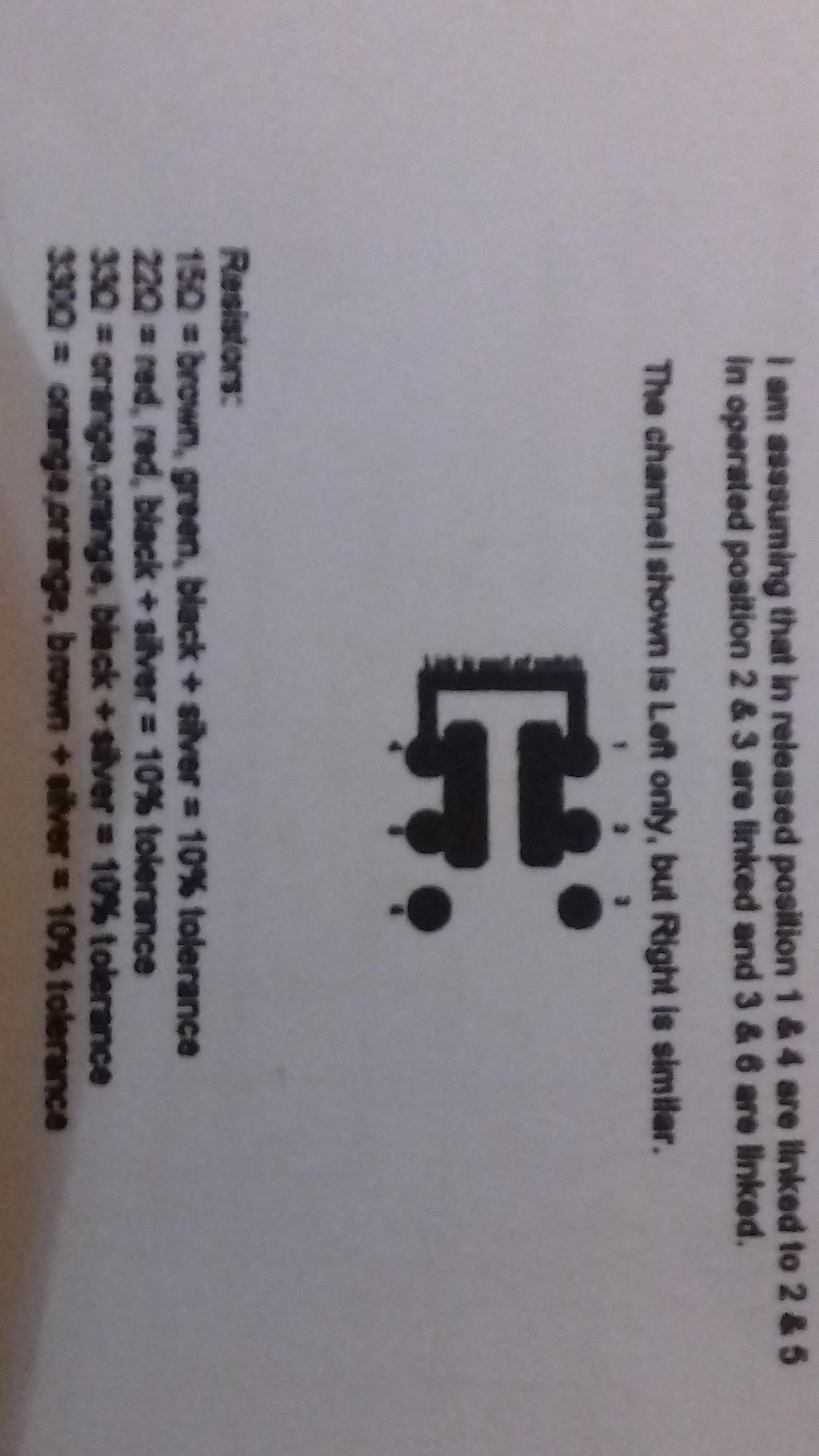
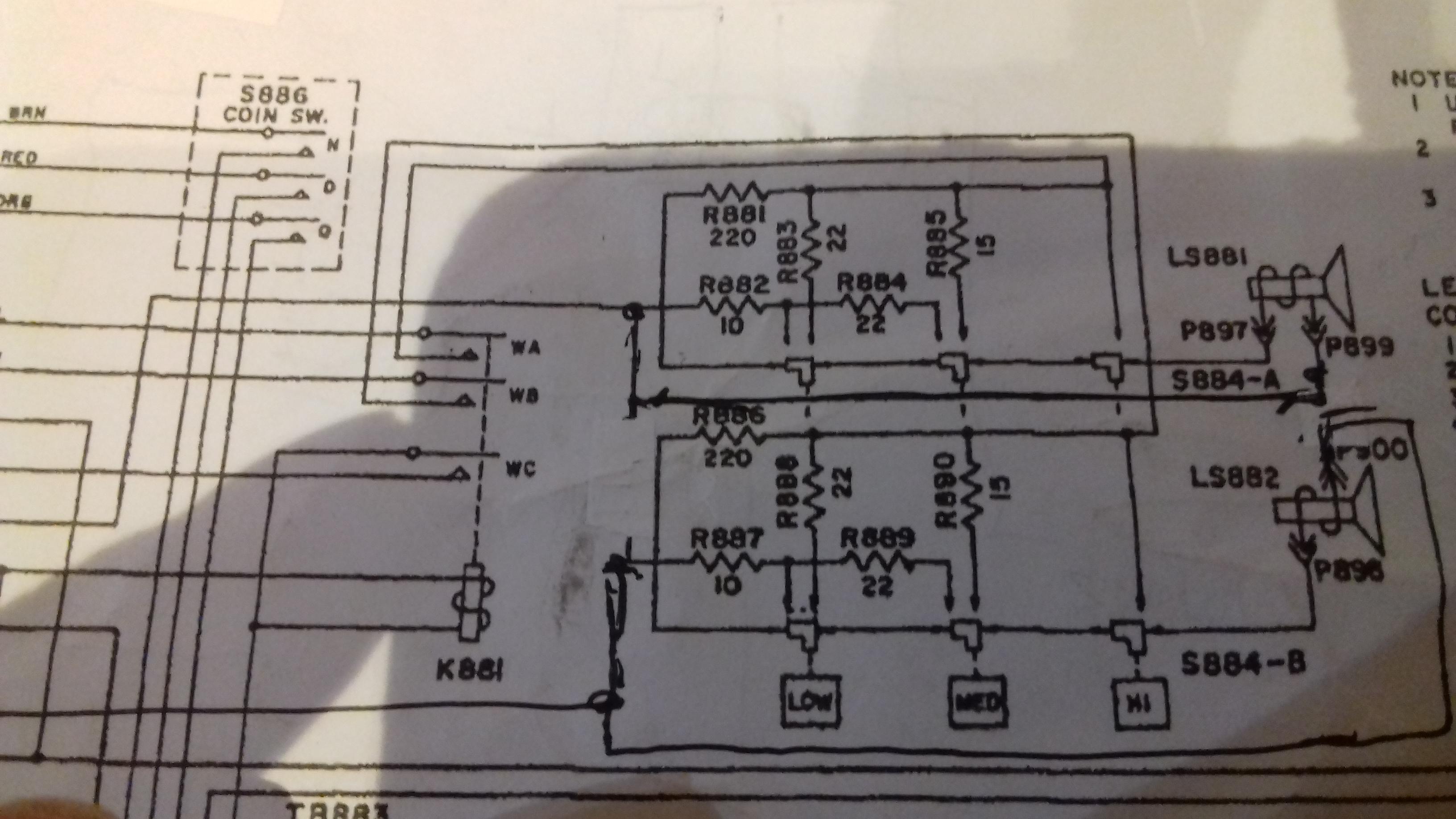
I have found various diagrams , one shows a modified version of volume controls switch, this is a section of the Seeburg SC1 wiring diagram. If compared to the original you will see the difference.
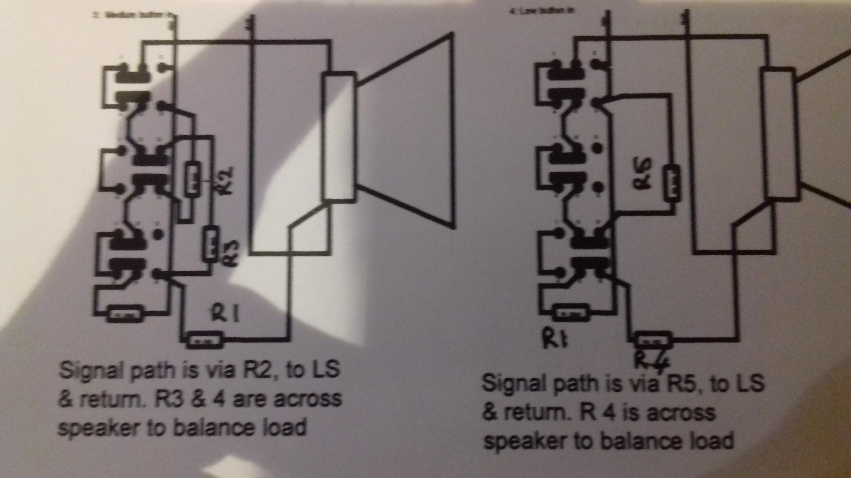
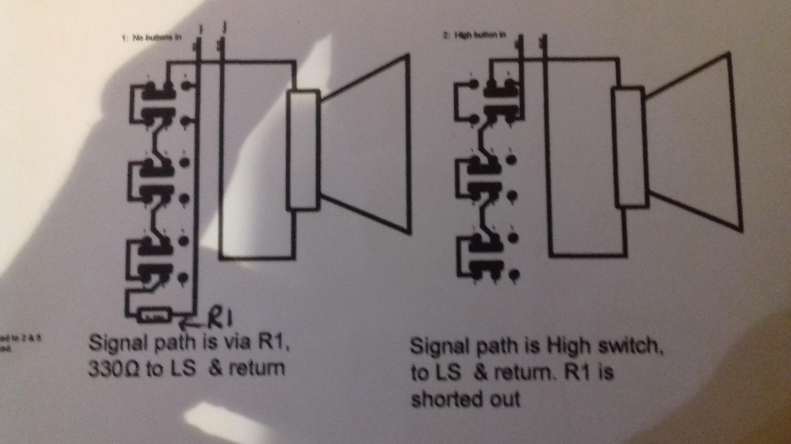
The other diagrams show the various circuit paths of the audio through the switches & there relevant resistors. It’s a while since I looked at these & rememberit taking me a while to get my head around how it worked! Sorry the first one is sideways , Hope they help.
Cheers Scudie
-
4 March 2019 at 23 h 19 min #45980Participant
Not sure if I have mentioned it previously but you can download a copy of the Seeburg SC1 manual from here on the website I think it’s under the Support section.👍
-
5 March 2019 at 0 h 47 min #45982Participant
Thanks Scudie!
I’ll have to see if I can decipher it now. Yes, I already found the Seeburg SC1 manual.
Thanks again!
Steve
-
5 March 2019 at 4 h 06 min #45983Participant
Scudie,
I got mine working! It turned out I had the ground wires coming from the volume control going to the wrong speaker. I thought I had tried it before but I may have mixed up the positive wires. Anyway it’s working now and I believe it’s wired just like yours only bypassing the relay.
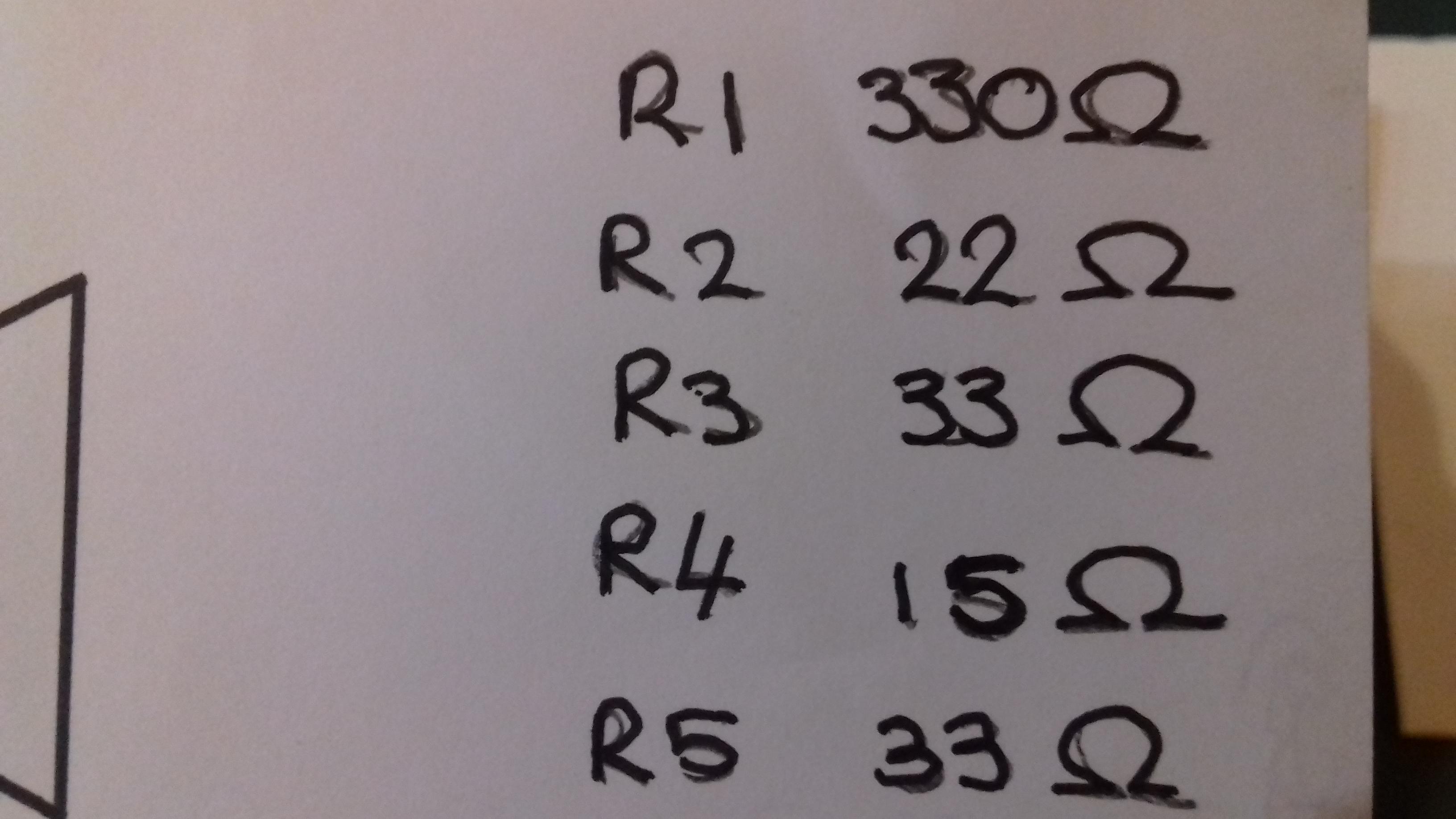
Interesting that the schematic shows two 22 ohm and one 220 ohm resistors but mine had one 22 and two 220 ohm resistors. Strange…
I made a couple of other modifications also. I replaced the 10 ohm resistors with 20 ohm resistors. That makes the change in volume a little more so a little more useable. I also clipped the connections of the 220 ohm resistors on the outside of the control unit. Now when no buttons are pushed in the volume is completely cut off. That will be handy when using a Bluetooth unit so there’s no echo effect because of the Bluetooth delay.
Thanks again!
Steve
-
5 March 2019 at 20 h 17 min #45984Participant
Hi Steve
Glad to hear that you found the problem & got it sorted, that’s an interesting idea by disconnecting the resistors thereby switching audio off with no buttons pressed, nice one.
Do you still have the humming from the left speaker?
Chears Paul
-
5 March 2019 at 20 h 33 min #45985Participant
I have buzzing in both speakers but it’s not too loud so you can’t really hear it when the volume is turned up at least half way. You don’t have any buzzing at all when the volume on the emulator is turned all the way down?
-
5 March 2019 at 20 h 34 min #45986Participant
And there’s no buzzing when using the Bluetooth through the AUX output.
-
7 March 2019 at 15 h 56 min #45991Participant
I did some more experimenting with different resistor values in the volume control to try and improve the range even more. The best combination I came up with was to replacing the 15 ohm resistors with 20 ohms (2×10 in series) and replacing the 22 ohm resistors with 43 ohms (10+33 in series). Now I’m getting about a 6dB reduction for the medium setting and another 6dB for the low setting.
-
10 March 2019 at 22 h 57 min #46004Keymaster
That’s really great. I have to keep trace of it to experience it on a SC1 in the future.
-
-
AuthorPosts
- You must be logged in to reply to this topic.